This has been a pretty good remote control for the swimming pool. I own one and my neighbor also owns one. My neighbor's system broke. After a bunch of troubleshooting and a call to the Polaris to confirm that her remote controller was trully dead. I decided it was time to try to fix her unit. After all, what is the sense of having a BSEE and never using it. Besides new swimming pool remote units are expensive. We both selected this home swimming pool remote control unit when we built our swimming pools as it seamed to be the best one the market at the time. It still is a pretty good unit and the prospect of spending a grand plus to replace it over a broken remote control unit just doesn't sound like fun. Swimming pools are supposed to be enjoyed instead of being at work to pay for them.
First of by dead we mean with a fully charged battery pushing any of the buttons causes nothing to happen. No screen light up, no buzzing sound from the unit, no nothing, zilch. If the unit does anything at all it could just mean that it needs a complete reseting. Just removing the battery usually will do the trick perhaps.
The first challenge was 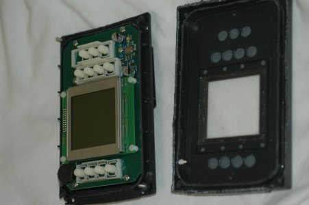
I got lucky on the first try and was able to get the case open without hurting any of the circuit. Once inside a few screws later I was into troubleshooting mode.
The unit appears to have bee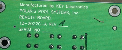
A quick reverse engineering of the circuit board revealed that the circuits consists of a max712 smart battery charger circuit using almost the exact same values as Maximum shows on their data sheet for this integrated circuit. Followed the batter charger circuit is Maxim 710 Step-Up/Down DC-DC converter power supply. Noticing the burned spots on the circuit board I was able to find that the switching transistor on the battery charger had gone to transistor heaven. After a bit of calculations I discovered that the original transistor was way undersized for the load it was being forced to do. I was able to find a proper sized component and installed it but even after I got the board running again I was not happy with heat dissipation of the circuit board so I built a poor man's heat shield around the transistor before final assembly.
After getting the battery charger working I then discovered that the DC-DC regulator also was not working. The problem turned out to be a burned out resistor that was also improperly sized for the amount of current going through it. A study of the Maxim data sheet found that the resistor was not really the proper component to use and a hunt through my junk box found an old inductor that I would work far better than the original resistor.
Here is the fixed board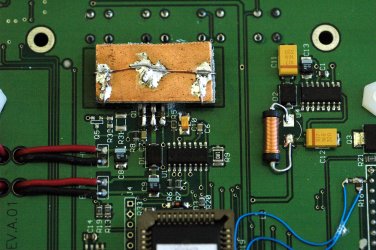
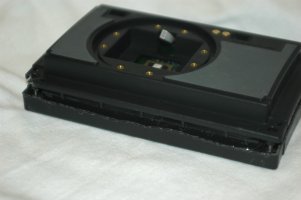
So all that is left to put the the case back together.
I was able to reuse the original screws and mate the top and bottom plastic pieces back together. The unit isn't water proof anymore but a plastic bag solves that problem. If I wished to make it water proof a bit of RTV would have done the trick.
So for about $3 worth of parts I was able to fix my neighbor's unit.
If you have a dead unit and want to me fix it, email me-- mike.sol1000@m3h.com. I make no promises. If I'm unable to fix your unit all that it would cost you would be shipping. On the other hand if I do fix it it will be far cheaper than buying a replacement unit from Polaris.
If you wish to try to fix your own unit and have questions feel free to ask.
Happy swimming!